I am happy to announce that my 3E, electric Honda HR-V is street legal!
It is the first converted street legal electric vehicle in Lithuania. And I'm proud of it.
The process was challenging and quite work consuming but I was working with good willing people from different institutions and we together were turning problems into solutions. Big thanks to them.
One of the results is 118 pages long technical documentation of converted vehicle containing lots of photos, diagrams and tables with the emphasis on compliance to EU standards for electric vehicles. I believe this work will help other EV builders in Lithuania to make the process much simpler.
Now I'm preparing for CO2 Green Drive initiative show which will happen in Vilnius on October 23rd. My 3E will be among other participants which can be seen here http://www.vilniusco2.lt/en/cars/
I'll put more info about CO2 Green Drive and details of recent work that was done on the car to make it finally street legal EV.
2010-10-19
2010-08-27
Video of driving 3E - Electric Honda HR-V
I have recently posted a video of driving my EV on YouTube. Put some music on it from local electronic music band "Mind Engineers" . Enjoy.
I am still working to make the car street legal. We had preliminary inspection with transportation experts and agreed on several main points to be done before final certification:
- Emergency disconnect "Red Button"
- Comparing information of cabin air heater element, brake booster and power steering between original components and new replacements
- Protection cover of power cables underneath the car from physical damage (stones, etc.)
- Marking on high voltage cables with with bright colour (orange or similar)
- Informing driver by sound if he's leaving a drive-active car
- Safety procedures modification for starting and running the car in accordance to EN-1987 standards
- Check the charging connector for compliance to EN IEC-62196
- Preparation of technical documentation of the modification
- Some other smaller ones
As I am the first one to go through such certification in my country it is a bit of learning curve for all of us. But I work with people who have good willing approach and we are gradually solving the problems in our way.
So I am quite busy to finalise these things and finaly get my car certified. I will update the blog with new posts of modifications as I go.
2010-07-02
Electromagnetic disturbances tests passed!
I have been working on paperwork to get my EV street legal recently. One of important tests required by state transport inspection is to pass required electromagnetic disturbances test in accordance to European Economic Comission (EEC) Regulation 10. Specifically relevant requirements are stated in sections 6.2 and 6.3 of this regulation.
The test was conducted by local state Communications Regulatory Authority. The tests done according to ENECE Addendum 9 to the 1958 Agreement E/ECE/324, E/ECE/TRANS/505: Regulation No. 10 - Revision 3.
Both narrowband and wideband tests Passed!
Now I am working with state transport inspectorate to complete the inspection of vehicle and register it as street legal electric car.
2010-05-15
3E - Ecologic, Economic, Electric; electric Honda HR-V in exhibition
I had 2 busy weeks lately: first - preparation for showing the car on exhibition BaltTechnika 2010, second - participation in exhibition itself. My friend Marius, professional designer, has prepared the design for the car and materials for exhibition. During that the new name for this car has developed - 3E - Ecologic, Economic, Electric which has become a logo of this car. So my working project name "HR-EV" is now 3E.
New web site has started http://www.emobilis.lt/ for the car and activity which is just basic info about the car and the controller for it which is named EVMS - Electric Vehicle Management System. This is the name for the development the management system which previously called BCMS (until I included the motor controller in it as well). Info in lithuanian was put first.
The exhibition was quite successful with a lot of attention from visitors and media. This might inspire further development of the product or some more EV conversions in our country.
Here are some photos from Exhibition.


Some more photos of the car outside:

The photos of components arrangement inside:


And here are some pictures of EVMS (Controller, BMS, safety systems in one) touchscreen display which is implemented on Windows mobile device Ipaq hx4700.
The display graphical user interface software is flexible so it can be arranged in many different pages with different indicators on each page showing the parameters sent from main controller module. The layout, indicators, colours, graphics can be adjusted to liking and match the interior of the car.
Here is the Main page showing battery voltage, current, power, energy, momentary and average consumption, distance traveled today and estimated distance left.

Here is the battery cells status screen showing voltage, temperature and balancing voltage of each cell plus average and total voltage of all cells.
Here is the consumption screen showing battery charge, estimated distance left, distance, energy consumption of this trip and today plus average and momentary consumption.

Here is the screen voltages. It shows voltage, current and power of main battery, motor and 12V battery plus position of accelerator pedal at the bottom.

This Charging screen shows charging stage. It shows voltage, current and power set for charger and actual. It also shows cells minimum, average and maximum voltages. Two buttons at the bottom allow you to select the charging rate: slow for 220V/10A socket and fast for 220V/16A socket.

Here is Temperatures screen which shows temperatures of controller (IGBTs power stage), motor, battery minimum and maximum, interior and exterior.

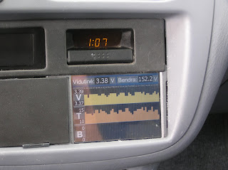
And lastly the main menu which allows to select you the information page you want. The time on stock car clock is wrong as I forgot to set it right :). Note the small card at bottom left? That is the SD card which carries the screen configuration and recorded parameters log files. It records the files constantly producing one file per day.

Here is a short movie of display in action:
New web site has started http://www.emobilis.lt/ for the car and activity which is just basic info about the car and the controller for it which is named EVMS - Electric Vehicle Management System. This is the name for the development the management system which previously called BCMS (until I included the motor controller in it as well). Info in lithuanian was put first.
The exhibition was quite successful with a lot of attention from visitors and media. This might inspire further development of the product or some more EV conversions in our country.
Here are some photos from Exhibition.


Some more photos of the car outside:

The photos of components arrangement inside:


And here are some pictures of EVMS (Controller, BMS, safety systems in one) touchscreen display which is implemented on Windows mobile device Ipaq hx4700.
The display graphical user interface software is flexible so it can be arranged in many different pages with different indicators on each page showing the parameters sent from main controller module. The layout, indicators, colours, graphics can be adjusted to liking and match the interior of the car.
Here is the Main page showing battery voltage, current, power, energy, momentary and average consumption, distance traveled today and estimated distance left.

Here is the battery cells status screen showing voltage, temperature and balancing voltage of each cell plus average and total voltage of all cells.

Here is the consumption screen showing battery charge, estimated distance left, distance, energy consumption of this trip and today plus average and momentary consumption.

Here is the screen voltages. It shows voltage, current and power of main battery, motor and 12V battery plus position of accelerator pedal at the bottom.

This Charging screen shows charging stage. It shows voltage, current and power set for charger and actual. It also shows cells minimum, average and maximum voltages. Two buttons at the bottom allow you to select the charging rate: slow for 220V/10A socket and fast for 220V/16A socket.

Here is Temperatures screen which shows temperatures of controller (IGBTs power stage), motor, battery minimum and maximum, interior and exterior.

And lastly the main menu which allows to select you the information page you want. The time on stock car clock is wrong as I forgot to set it right :). Note the small card at bottom left? That is the SD card which carries the screen configuration and recorded parameters log files. It records the files constantly producing one file per day.

Here is a short movie of display in action:
2010-04-30
Electric car is finished, final touches and bureaucracy left
Well, I can say that my electric car conversion is finished. It is running fine, controller working well, BMS managing the batteries during charge well, display showing main car and batteries parameters on touchscreen, stock RPM, fuel and temperature gauges on stock dashboard show meaningful values, drive-testing does not show any more quirks to be fixed. There are cosmetic touches left to be done here and there. They would be done during the preparation for this car presentation to the public on May 11th. This is the main activity now. Of course there is no limit to perfection but I'll need to stop myself at some point of "good enough". When car is prepared for presentation I'll make a video of it from all possible aspects I will think of. Until then I would ask for your patience and staying tuned.
Oh, yeah, another important thing after presentation is to go through bureaucracy to get finally registered as roadworthy electric car. This part could be interesting. I think it would be still the first one converted in Lithuania regardless of these big delays I had.
Oh, yeah, another important thing after presentation is to go through bureaucracy to get finally registered as roadworthy electric car. This part could be interesting. I think it would be still the first one converted in Lithuania regardless of these big delays I had.
2010-03-03
Power Steering
Power steering is also part of this EV conversion project and I was looking for some time through feasible options from direct electric power steering like in Honda S2000 to traditional hydraulic pump driven by some electric motor. I decided to use the electric power steering pump from Peugeot 307 or Citroen C4. These are integrated motor-pump units. In essence you have to connect it to 12V on one end and hydraulic hoses to the other.
I connected this unit to my Honda's stock power steering column using Honda's own old high pressure hoses. Of course the hose mating adapters needed to be manufactured as all the dimensions of Honda and Peugeot don't match. My friend Gytis helped in it.
The electric connectivity is slightly more complicated than just connecting to 12V. This is because the pump is quite intelligent beast made by Siemens. It has two connectors: 2 thick pins connector (ground and 12V battery - no brain needed here), other is 9 pins connector which was a bit more of fun. If you just connect +12V battery on 2 pin connector nothing happens, and pump does not start. It surely waits for some signals on another 9 pin connector.
After looking through all info I could find on Peugeot on Google I found next to nothing of something useful how these pins are used. I only found that one red wire (5) goes to ignition switch, other two blue (1) and beige (6) to main control block under steering wheel, then other red (4) goes to ABS, other beige (9) goes to block BSI which is controlling the engine and the last white is diagnostic. No info about how are these signals are behaving. In essence this power steering pump is able to adjust its power in reaction to what steering wheel and ABS do but no info how.
So I've done some experimenting with the pump I found that to start you need to connect and keep connected +12V to ignition (5) and make a short +12V pulse on pump enable (9). Then the pump just runs at full power continuously. It is ok for me as Honda's stock hydraulic power steering also operates at full power when engine is running.
So to make long story short to use Peugeot 307 power steering pump you need to connect it's fat 2-pin connector's pin 1 to 12V battery +, pin 2 to 12V battery - (chassis) and 9 pin connector's pins 5 and 9 tied together car's to ignition key's wire Ign1 which becomes +12V when key is turned to "On" position. This way the pump runs when you need it.
Below are some bad quality mobile photos of the pump itself and manufacturing of it's top mounting bar and lower holding arm.


After putting everything together I got nice and smooth power steering feel of the steering wheel.
Mission accomplished.
2010-02-27
Mounting battery boxes
It has been a long pause again in my blog - again. The main reason is that blog update stands not on the top of my priorities list among family, main job, and actually working on HR-EV. I reckon if I would have worked normal working hours it would have taken me around 4 months. But now we are approaching 2nd anniversary of the project. Anyway, it's good that it is moving.
This time I want to show the mounting of battery boxes. Apologies for bad quality photos taken from my mobile because camera died when I needed it and I've been to busy to look for another camera.
The battery boxes are mounted on two 20x20x3 stainless steel angles: one in front bottom and one in rear top.
I used most of the car's stock bolt places on the chassis to fasten front rail using just one additional which was welded in. Rear rail was fastened to bottom sheet of the car where the spare tire is placed.
Here is the picture of one box mounted on the rails.
 As you may possibly see the front rail is basically hanging on 4 20x3mm stainless steel bars bolted on top to chassis and bent around the angle bar at the bottom and welded to it. This construction allows the angle to swing a bit which is good as you don't have to be dead precise when making these rails. Being very precise in garage conditions is quite difficult. Lateral stability of this bar is achieved by the fact that boxes are bolted to it and boxes themselves are fastened at rear. The other stability element is the 0.8mm steel cover which is bolted to car and to small legs which were formed from the 20x3 bars bent around the angle ( you can see these three legs on the photo above).
Here is the picture showing the rear of the box and I hope you can see the angle bar in dark top left corner of the photo.

Here is the view from inside the car's trunk where the spare wheel is placed.

You can see 4 bolts caps in a row. That's how the rear bar is attached. Simple, isn't it? Well there are 2 additional long bolts on both sides securing the very ends of the rear rail angle. These are not visible on this photo.
On the above photo there are 4 cut opening providing access to boxes terminals to interconnect them together. You can see couple of LEDs lit up on the left which were shot when BCMS was scanning the cells.
Below are couple of very crappy photos which taken with the same mobile camera. The sad fact for the hobby project is that it is rarely possible to work in daylight as in winter night is starting early and job is usually done after main work. I will re-take with proper camera and place here. I promise :)
Here is the view from front left with all battery boxes in place. You can see the thick cable running prepared to be connected.

Here is dark view from the back bottom view of the batteries (that's how you define darkness :)

Here is the dark view of the batteries on the front rail when viewed from the car front.

Here should be photo of the boxes with protective steel sheet installed but I was too tired to remember to take a picture with it. Next time, when I bring the car on the lift again.
This time I want to show the mounting of battery boxes. Apologies for bad quality photos taken from my mobile because camera died when I needed it and I've been to busy to look for another camera.
The battery boxes are mounted on two 20x20x3 stainless steel angles: one in front bottom and one in rear top.
I used most of the car's stock bolt places on the chassis to fasten front rail using just one additional which was welded in. Rear rail was fastened to bottom sheet of the car where the spare tire is placed.
Here is the picture of one box mounted on the rails.

Here is the picture showing the rear of the box and I hope you can see the angle bar in dark top left corner of the photo.

Here is the view from inside the car's trunk where the spare wheel is placed.

You can see 4 bolts caps in a row. That's how the rear bar is attached. Simple, isn't it? Well there are 2 additional long bolts on both sides securing the very ends of the rear rail angle. These are not visible on this photo.
On the above photo there are 4 cut opening providing access to boxes terminals to interconnect them together. You can see couple of LEDs lit up on the left which were shot when BCMS was scanning the cells.
Below are couple of very crappy photos which taken with the same mobile camera. The sad fact for the hobby project is that it is rarely possible to work in daylight as in winter night is starting early and job is usually done after main work. I will re-take with proper camera and place here. I promise :)
Here is the view from front left with all battery boxes in place. You can see the thick cable running prepared to be connected.

Here is dark view from the back bottom view of the batteries (that's how you define darkness :)

Here is the dark view of the batteries on the front rail when viewed from the car front.

Here should be photo of the boxes with protective steel sheet installed but I was too tired to remember to take a picture with it. Next time, when I bring the car on the lift again.
Subscribe to:
Posts (Atom)