2009-05-10

BCMS and Battery Boxes

I caught some nasty flu on Thursday and needed to sit at home during almost whole weekend. Luckily wife with baby were out during it - visiting parents, so they were safe. Once I was feeling better I resumed some works on electronics and programming. I sent an order for battery module 45 PCBs. I expect to have them on Friday.

I've started programming the PDA graphical user interface. I'll use IPAQ or similar PDA with PocketPC 2003 system which will be mounted in the dashboard and give all information about car, batteries, temperatures, etc. For starters I just made it read the serial output sentences which are generated by BCMS. The protocol is NMEA which is widely used in GPS devices. I've created some custom sentence names which are used in my BCMS. The idea is that I'll have all parameters information along with GPS position of the car which will help car performance analysis after. Below is PDA emulator's program's simple screen which reads the data from serial port and displays in simple text fields. The parameters displayed are actually measured by BCMS.

When I got better on Sunday afternoon I went to garage and made a short session working on battery boxes. I welded the top mounting flange with one hole for initial mounting of the box. I also welded a M8 bolt part at the botom of the box where the batteries are being put. This bolt will be used to secure and press the batteries with V-shaped frame shown below. This will prevent any possible swelling of the cells.

Next will be a lot of grinding of the boxes to remove excess metal from the welds and improve aesthetic view. Nasty part will be cleaning the welds in inner corners of the boxes as it is not yet done properly. Then I will put stainless steel sheet into the boxes walls and they will be almost finished. Almost... There will be plastic retainer bars inside to stop cells from bouncing in the box. And also some plastic or maybe metal sheet cover on top of the boxes with openings at both ends to allow access for boxes interconnections.

2009-05-04

Battery boxes and Control box

Battery boxes

As mentioned earlier I decided to place all the batteries underneath the car where the fuel tank used to be. After making measurements thinking and modeling I chose to make battery boxes to be fitted from underneath the car thus preserving most of the body structure and not weakening it with serious modifications. The reason is that I am thinking ahead about how I would present the car to inspectors who would be checking it to make street legal. Less modifications to the frame - less problems and questions asked.
So, I will make batteries trays/boxes fit and secure from underneath making only few openings from inside to complete the wiring once the boxes are placed in. There will be 5 battery boxes each holding 9 cells. Each box gross weight will be approx 32kg so it will be manageable to lift it to the car from underneath and secure it by hands of two persons. So you will be able put the whole 160kg of batteries box by box.
Here is the sketch of the battery boxes made with Google SketchUp:

Each box is a frame of stainless steel angle 20x20x3 with 0.8mm stainless steel sheet walls protecting the batteries from outside elements like water, sand and stones (remember they will be hanging under car's belly).
The production of boxes has started. I have made the welding jig to make their geometry solid. Without it would be very difficult to weld the steel boxes with decent precision and correct geometry.

Here is one of the boxes fit test with 9 ThunderSky cells. The cells have their contacts covered with tape - you don't want to short circuit expensive cell, don't you?

Control box


Control box is designed to hold all electronic equipment inside and provide a heat sink for controller and down converter. First of all I don't want any sensitive electronics or high voltage circuit hang outside where the could be touched by water, dirt or anyone's non-careful hands. Safety first. For example a session in car wash could lead to serious components damage or even fire in unfortunate circumstances. Therefore I decided to put all such pieces in one safe place - control box.
The control box will hold Kelly controller, controller cooling fans, DC 144V/13.8V down-converter, main contactor, circuit breaker, shunt resistor, throttle hall converter, multiple 12V control relays and fuses and BCMS master board. It will have two thick cables coming in from batteries, two going to the motor and low voltage signal cables going to many places.
The box is made from 10mm aluminium plate which makes base, 3 walls and internal spacer. The plates are bolted together by M5 bolts. The cover will be from 0.8mm stainless steel sheet.
The inside is divided by internal spacer wall into two sections: high voltage/power section and low voltage section. The sketch is shown in picture. There are two big black fans on top which are placed on the opposite side of the wall where the motor controller is placed for maximum heat dissipation effectivenes. The black box on the opposite side of the controller is DC down-converter. Both controller and converter terminals are placed so that they go out to the high voltage connections subsection on the upper right side of the box. This subsection is separated by plastic spacer plate which isolates the connections subsection to prevent any water or dirt entering there. Contactor, shunt and fuse are shown in this subsection. The subsection below contains BCMS board on the left and throttle pot on the right. Throttle handle is attached on the outside of the box. There will be gas cable connected to it.
The box will be put in the car above the motor in approximate location shown in sketch below. I hope you have enough imagination to see the yellow front of the car, black tire, red motor below and gray brakes cylinder assembly :).

Production of the box has started. The aluminium plates were cut (believe me it is daunting when you don't have the disk saw powerfull enough). A lot of drilling and threading was made.

Some power wiring was made with thick copper bars covered in yellow heat-shrink tubing. Production of each bar to about 1 hour - it looks small but eats your time very quickly.

A bit closer view. Note the two big holes drilled in the base - that's where the thick cables will go to the motor.

That's it for now. Some progress, not too much as I am really struggling to find time to sneak into garage and do some work on my HR-EV.

2009-03-24

Electric vehicle brake arrived!

It's been a while since my last post about HR-V conversion and have you been questioning why? It is because the "Electric vehicle brake" has arrived on Feb 21st. The brake is 53cm long and 3.56kg heavy :)

That's right- I have a firstborn child, a boy whose name is Herkus!

Here is my son Herkus first days of his life in this world.

Here is Herkus and me. No, I'm not Chinese - it is less sleep that I got during these days.

He is an EV brake but he is not an EV stopper and I believe the day will come when he will be an EV accelerator. I continue working on EV although naturally the speed is less with the brake on :)
I've done good progress on several things, which I will post more pictures and detail in new posts shortly:
- Battery Voltage and Current measurement circuit is made and programmed which is communicating to BCMS master module to report measured voltages and currents. Voltage measurement step is 0.2V up to 204V. Current is measured up to 512A with 0.5A steps.
- Made measurements and brainstorming about battery placement in the car. Decided to put all batteries in 5 trays with 9 cells each where the fuel tank used to be - plenty of space there in HR-V. The trays will be fit from below so car lift would be needed. Made one battery tray frame from stainless steel angles to verify the concept.
- Designed the box where controller, contactor, accessory charger, shunt, accelerator pot and other electronics components will be placed securely and safely without any potential of high and low voltages to be touched by water or uncareful hands. Already built the main parts of the box and ready to place the components in. Now working to finish the controller box and start fitting the components inside.
- As Gytis has moved from his garage I now continue working in my small garage below my apartment block. It is small, much less equiped but is much easier to come down to work in the evenings.

Will put more info and pictures in upcomming posts. Stay tuned!

2009-01-23

Batteries are home!

Long waiting is over - batteries arrived to where they belong :) I've received 45 TS-LFP90AHA batteries for my HR-EV after more than two months waiting. They've been sailing from Shenzhen in China to Hamburg in Germany and then to Klaipeda in Lithuania - a long trip.
I've taken them from warehouse after customs clearance in my trusty Subaru.

Shortly after I've opened the boxes to see what's inside. I found nicely printed manual and quality certificate. Quality certificate has lots of useful information in Chinese :) User nice manual was the same as pdf available from ThunderSky site. Beneath white cover I found a surprise - batteries :).

Here's a video shot from breathtaking moment :-D


The look at the battery itself.

All the batteries read voltage of 3.30V or 3.31V - GOOD!

The road to the future :)

While I was waiting for the batteries I've been working a lot on BCMS prototype electronics and programming. Here's a brief update about the progress:
- RealTime OS launched on ATmega640
- Serial communications programming wired and programmed - talking to PC now
- Connected to battery modules (at bottom) via opto-coupled serial port and launched battery voltages reading for BMS operation. It ballances Lithium Polymer cells within 0.02V of each other.
- Wired and programmed MLX90215 sensor (small board assembled on the left) so I can measure current of up to 10 Amps to test the concept. The finished sensor will be able to measure up to 700A from batteries and to the motor.
- Wired a contactor control circuit (simple IRL3705 MOSFET switch) and programmed its control
- Wired and programmed 12V line voltage measurement using mega's ADC
- Wired and programmed DS18B20 sensors for BCMS, Controller, Motor, Outside, Inside and Batteries temperature sensing.
- Started wiring a slot for SD/MMC card where the HR-EV's parameters log would be stored
- Some small stuff...


There are many things left to do on electronics until I start the first test of the car:
- Finalize battery module schematics, programming and PCB design, try final prototype on real battery and then order parts and PCBs
- Make schematics/wiring and programming of opto-isolated battery voltage measurement
- Make motor RPM sensor using MLX90217, wire it and program RPM calculation
- Wire gearbox speed sensor and program the speed calculation
- Make throttle sensing and control schematic and programming
- Wire digital inputs like key switch, charger on, throttle idle, gearbox neutral etc.
- Program the safety and control. Basically it should shut off main contactor if any important parameter goes critically off.

Well, there is much much more. One thing - I still haven't got the charger. In the beginning I thought about Zivan NG3 but now I'm not so sure. Still have to decide... and order it.

Of course there are lots of mechanics works to do as well. I'll update as I progress.

2009-01-06

Motor holder made and installed

Last couple days I've spent manufacturing the motor holder from accessory end to remove any temporary hanging arrangements. The part is quite simple but to make it right took some time. As I am using native rubber pads to attach the gearbox and motor to the car body frame. I've seen some builders attach the motor with hard parts but I don't like such approach. Even if there is virtually no vibration from electric motor the rubber pads help to remove the stress from holding parts and dampen torque shocks which should give even smoother operation.
This decision complicated the task of deciding on holder's measurements. The rubber parts stretch and you cannot be sure what measurement of the holder would be the best. Even if this is not critical I want to build things as right as possible from engineering point of view for this conversion without cheap shortcuts.
I decided that I would trust Honda engineers to determine electric motor fitting position. The removed 1.6l Honda IC engine weighted over 90kg. The electric Warp 9 is around 80kg which is quite similar. So I took measurements from ICE native holder part picking crankshaft center at the front as position reference. Then I used Warp9's CE shaft center to calculate the required part dimensions which would hold the electric motor in the same attitude as original petrol one. This measuring and design drawing alone took few hours. After that there were series of operations of metal measuring, cutting, grinding, drilling, sanding, welding, trial-fitting, grinding, sanding, painting and assembling (this is simplified procedure :).

The part turned out ok - approved by sleepy Baja below.

And here ar some photos of it installed - no more temporary attachments. View from car front.

From below

And from top.

Looks alright. We had some debate about thickness of the flat steel plate. But after trying to mentally model the forces applied to this part we came to conclusion that this thickness is definitely enough as the load is distributed through bigger area of it.

That's it for now - motor is installed safely. It gets to -20 Celcius at nights and its no fun working the garage. I'll focus on BCMS electronics now until it gets warmer or I need to remove the dashboard for instruments connection to BCMS.

2009-01-01

Motor installed, HR-EV has made her first run!

The end of 2008 was really busy working on my HR-EV. I've reached one major milestone of the project! But let's go in sequence.
I picked up the shaft coupler disk and spacers from workshop where they've been thermally hardened.
I've marked the spots for two fixing nuts on motor's shaft and drilled two dimples on both sides where the coupler disk's fixing bolts would sit in.
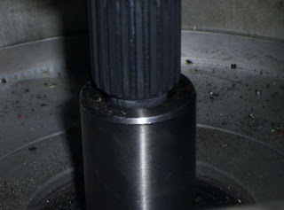
Next we put adapter plate spacer disk on the motor and pressed on the shaft adapter disk onto Warp9's motor shaft. We used 20-ton garage press to press it on. It was going stiffly but smoothly - it wouldn't go anywhere. Below Gytis is happy with the result :)

Here is the closer view

Then I assembled the shaft coupler on it and locked the coupler disk on motor's shaft with two hex fixing bolts. I used thread locking glue to make fixings bear the vibration.

And then I bolted on the gearbox adapter plate using the imperial/metric threaded studs and secured everything with thread locking glue.

A closer view

Then I've put the gearbox on and secured it with the bolts. The shafts and alignment rings fit like a glove without a fight. Phew, what a relief ... :)

Then my photo camera battery died and I used the video camera to shoot the further process. On this occasion I've compiled a small video from latest material together with some old video footage from the progress on HR-EV. If they say a picture is worth a thousand words then video should be worth a million. This is my first published video for this project. Have fun :)


In short later that night I've installed motor and gearbox in Honda and did the trial again using battery charger.
Then next day I took 100Ah 12V lead acid deep cycle battery and put it in HR-EV. I've wired it to motor via contactor relay. The relay is activated with simple pushbutton switch pressed by the driver :) No controller yet. This allowed to make the first ride in HR-EV and it will be used to drive the car into garage on its own power when needed. This is because Gytis' garage has to earn money working on other customers cars while HR-EV is an after-work hobby activity slotting in when car lift is free, etc.
And of course this allowed to have some taste of EV grin :)
This is quite symbolic as it was done on the last day of 2008 and I have had really nice feeling meeting the new year.

Happy New 2009 Year to All!

2008-12-28

Motor and gearbox mated, shafts not yet

I've done some good progress on motor and gearbox works. There was a great deal of help from my friend Gytis who runs the garage I'm working in on my HR-EV!
I've got the manufactured parts from workshop: gearbox adapter plate spacer disk, shaft coupler flange disk, 8 spacer rings for clutch parts assembly and 4 studs for motor which have 3/8 abnormal thread on one end and normal M10 on the other :) Manufacturing cost me around $250 which was not cheap but much less than original quote I've received. Although I couldn't avoid quirks which I'll have to sort with the workshop guys tomorrow.
The quirk was manufactured shaft coupler disk. It looked alright at first glance.
But when trying to bolt it to clutch parts the holes were not aligning by some 2mm! Initially I thought I've made an error making measurements or the drawing which was given to the workshop. I've measured clutch holes positions again and got 47mm from the center. I took my drawing and it said 47mm too.
The holes on actual part were 45mm from the center. So I'll have to bring it workshop for re-drilling the holes in correct places offsetting them by 45 degrees. I could have done this myself but I paid healthy money for it so I should expect the work to be done for it. That is not counting the semi-damaged part. This stopped the works on it for the weekend but we could still progress with gearbox adapter plate.

We finished the thick motor spacer disk holes and studs for them so they fit tight in their places. For now just placed them on copper grease for easier work while working on center alignment. Later we'll put them on bolt glue in the motor so they stay firmly in their places in motor.

Next we drilled the holes in thinner gearbox adapter plate and mated it to gearbox.

After this we attached a circular our own assembled drawing device to gearbox shaft and drew the circle rotating the gearbox shaft by clutch part.

Then according to drawn outer line placed the thick motor spacer disk and aligned to match the center position. Our estimated centering error with this method should be something like 0.1-0.3mm which should be fine for this assembly using clutch spring damper. The thick spacer holes were used as drill guides for drilling the holes in exact locations for thinner one.

After that we put motor vertically and put gearbox on it.

You can see that gearbox shaft goes inside motor's shaft end hole as was designed leaving 2mm space. Shafts centers alignment looks ok. We'll have to check it once we have the shaft adapter disk corrected tomorrow.

And from a bit different angle
Next we'll finish shaft parts and mate the shafts together. Then it should be fairly easy to put the gearbox and motor into the HR-EV. I hope we can do this before the New Year to have a stronger reason to celebrate :)