2008-12-28

Motor and gearbox mated, shafts not yet

I've done some good progress on motor and gearbox works. There was a great deal of help from my friend Gytis who runs the garage I'm working in on my HR-EV!
I've got the manufactured parts from workshop: gearbox adapter plate spacer disk, shaft coupler flange disk, 8 spacer rings for clutch parts assembly and 4 studs for motor which have 3/8 abnormal thread on one end and normal M10 on the other :) Manufacturing cost me around $250 which was not cheap but much less than original quote I've received. Although I couldn't avoid quirks which I'll have to sort with the workshop guys tomorrow.
The quirk was manufactured shaft coupler disk. It looked alright at first glance.
But when trying to bolt it to clutch parts the holes were not aligning by some 2mm! Initially I thought I've made an error making measurements or the drawing which was given to the workshop. I've measured clutch holes positions again and got 47mm from the center. I took my drawing and it said 47mm too.
The holes on actual part were 45mm from the center. So I'll have to bring it workshop for re-drilling the holes in correct places offsetting them by 45 degrees. I could have done this myself but I paid healthy money for it so I should expect the work to be done for it. That is not counting the semi-damaged part. This stopped the works on it for the weekend but we could still progress with gearbox adapter plate.

We finished the thick motor spacer disk holes and studs for them so they fit tight in their places. For now just placed them on copper grease for easier work while working on center alignment. Later we'll put them on bolt glue in the motor so they stay firmly in their places in motor.

Next we drilled the holes in thinner gearbox adapter plate and mated it to gearbox.

After this we attached a circular our own assembled drawing device to gearbox shaft and drew the circle rotating the gearbox shaft by clutch part.

Then according to drawn outer line placed the thick motor spacer disk and aligned to match the center position. Our estimated centering error with this method should be something like 0.1-0.3mm which should be fine for this assembly using clutch spring damper. The thick spacer holes were used as drill guides for drilling the holes in exact locations for thinner one.

After that we put motor vertically and put gearbox on it.

You can see that gearbox shaft goes inside motor's shaft end hole as was designed leaving 2mm space. Shafts centers alignment looks ok. We'll have to check it once we have the shaft adapter disk corrected tomorrow.

And from a bit different angle
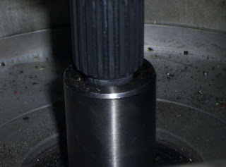
Next we'll finish shaft parts and mate the shafts together. Then it should be fairly easy to put the gearbox and motor into the HR-EV. I hope we can do this before the New Year to have a stronger reason to celebrate :)

2008-12-23

Adapter and BCMS works ongoing

The gearbox adapter production is in progress although not as fast as I would have liked. The gearbox plate was cut to gearbox contour with UHP water cutter. Spacer produced on lathe. Adapter disk production is on final. The gearbox was brought to workshop for all parts mating. Sorry - no pictures yet. I hope I'll collect it before Christmas and install motor straight after Christmas.
I was fighting with BCMS Atmega640 over the weekend and could not get it running stable - it was driving me nuts. And yesterday night I just came with fresh view and approached the problem from different angle. I found the root cause which was quite silly that I don't want to talk about. I should get it running OS performing basic comm tasks in few days now. I'd like to get it talking to my battery modules prototypes and to PC. Then I'll focus on building the main contactor control, temperature, voltage and current measurement circuits as these would be required soonest to measure main parameters for safe testing.

2008-12-18

Motor adapter and BMS works ongoing

Last few days been involved in other activities and little time was left for the EV project. Anyway I had time to arrange all activities for gearbox adapter and shaft coupler. I've purchased the materials and brought them to workshops. Realistic timing is to have the parts made for the beginning of next week.
There was some progress on Battery Module PCB design. I've made it to the point where it is nearly finished and I could finalize it and send the design files to PCB manufacturers. But I've decided to wait until my batteries arrive and make a final fit check on actual cell before ordering PCBs production. My batteries are still sailing to me and according to the documents I should expect them around December 26th.
So far my nearly finished design is shown below. Just top copper is shown for clarity.

For now I'll put it asside and will resume work on master module on recently received ATmega640 MCU and various sensors. I've decided that I won't produce any PCB for master until I have fully functioning prototype working in the car. Only then I'll produce the PCB mostly with SMD components for the car computer.
Below is the initial board with MCU on adapter board. It will start growing with various components around it quickly and and I'll adapt the Real-Time Operating Systerm (RTOS) for it as I did for ATmega16.

2008-12-15

Motor adapter design homework

After disappointment with quoted workshop all-inclusive services price I took the adapter production process control to myself. I've disassembled the clutch by taking the outer friction disk off and grinding off the pins holding three metal pieces together. You can see the angle grinder marks around these holes.


These three pieces will be bolted with M8 bolts to the Warp 9 shaft adapter steel disk which will be manufactured in different workshop according to my drawing.

The whole assembly will look like this:

The two simplified clutch parts are yellow with orange spacers keeping them apart. They are bolted by four M8 bolts to the green shaft adapter disk.
The light blue are the motor-gearbox adapter plates. The thinner one is 16mm durable aluminum that bolts to the gearbox following its contour. The thicker one is the 25mm spacer disc to provide required spacing between my HR-V's gearbox shaft (purple) and Warp 9 shaft (red). The thicker one is quite simple round disk part and I've prepared the engineering drawing for its manufacture.
The thinner one must follow the contour of gearbox so I have to prepare a template for it.

Template was taken by putting the A2 size thick white sheet of drawing paper on the gearbox, making the guide holes so it does not move and then hammering on the edges with a rubber mallet so it left clear imprint of edges. As you can see the gearbox is still unwashed and it left clearly visible marks on the paper. I've then drawn the required plate contour along these edges making clear where will I need the cut. I've also marked 18cm opening in the center around shaft position. I've tried to make quite precise but the precise location is not of high importance as it would be corrected after motor and gearbox shafts center alignment. And I've got a bit dirty but clear template for adapter plate.

Next I'll take the required materials from supplier and bring these pieces along with drawings and templates to various workshops for manufacture. The gearbox adapter plate will be likely cut with UHP water jet cutter. Other parts are easily done on lathe bench.
If I'm lucky I might be able to collect all manufactured pieces this week and start motor installation on the weekend.

2008-12-10

Shock from workshop!

Just got the quote from metal workshop about motor-gearbox adapter plate and shaft coupler production. They've quoted the sum equivalent to around $700-800 for materials and works for this not so complicated product! I really hate when someone is trying to rip me off just because they see that the project is not cheap and quality is needed. I'll skip their offer. Anyway I'll have to look for another workshop or other option to produce the adapter plate and coupler.

2008-12-09

More progress on battery module

Battery module design is being finalized with additional details for final production which were not needed in prototypes. Added the parts such as optional pulldown resistors, optional shunt LED, optional optocouplers and connector for master. Few minor changes still remaining but it is almost there and PCB design is half-finished.
If someone's watching this blog I know they'll have questions about two serial connectors and optocouplers. So I'll explain it now.
Two serial connectors are designed in such a way that wiring the the boards should be easy with single short wire going from cell to cell. You'll get the idea when I finish and post PCB design.
Optocouplers are not needed on all cells except the lowest and the highert in the chain. The lowest cell (the one having minus terminal running to the controller) will have the board with U2 optocoupler and J2 connector for serial input. The highest cell (with plus to controller) will have U3 uptocoupler and J2 connector for serial output. This saves the cost by needing just one PCB design and fewer components on it and the area of the PCB as connector J2 is shared.

2008-12-08

Sensor chips arrived

My Melexis MLX 90215, 90217 and Allegro ACS754LCB-100-PFF sensor chips arrived:


They are kind of urging me to finish the work on battery modules and get back to BCMS master module design and prototyping. The functions of these received chips will be following:
  • MLX 90215 will measure the high currents (up to 650A) from batteries and to the motor.
  • MLX 90217 will measure the RPM of the motor on teethed gear mounted on the accessory shaft of my Warp 9
  • ACS754 will measure the charging current, DC/DC converter current and accessory battery draw current

2008-12-05

Motor arrived and works started, BMS prototype in progress

My Warp 9 motor arrived in November - heavy beast. I've taken the ICE out from Honda. The gearbox and Warp9 were taken to metal workshop to produce the adapter plate with perfect center alignment. Adapter plate will be produced from 12mm aluminum sheet with the 30mm spacer for the motor flange. No clutch. Shaft adapter will be done from original clutch disk part bolted on steel disk mounted on Warp9 shaft.

As told earlier I will make my own integrated Battery management and Car management system with instruments. So far made following progress on it:
  • Battery Module prototype made and programmed.Tests ongoing on model Lithium Polymer batteries. It is nicely balancing the 3-cell pack controlled by PC software via serial link. One module schematic is shown here:It is derived from a nice project being developed by Peter Perkins at http://www.batteryvehiclesociety.org.uk/forums/viewtopic.php?t=1245 .
  • Once I finish testing I'll design and order PCBs along with all electronic parts needed for them.
  • Master module prototyping started with real-time OS launched. Comms and several sensors tested. The core system will be based on ATmega 640 microcontroller. Interface will be provided on Pocket PC display running the GUI software which communicates to master module and displays graphical result. The screen will be integrated in the dashboard to blend into interior design.
  • Ordered more sensors chips to have various measurement inputs.
45 TS 90AH batteries were ordered and sailing to me.

Equipment arrived since last post:
Motor: NetGain Warp 9
BMS: various chips and sensors

Ordered:
Batteries: 45 Thundersky 90Ah LiFePO4s
Vacuum pump: Mes-Dea ( haven't arrive yet)
BCMS: various sensors

Need to decide and order:
Battery charger: haven't decided yet
BCMS: haven't decided which cheap Pocket PC to take as a basis for dashboard screen
Power steering: would like to find an electric steering actuator similar to used in MGs

Work done:
ICE taken out. Warp9 adapter plate started. BMS battery module schematics design and programming almost finished. BCMS design guidelines decided. BCMS master module prototype started. Simple PC software for managing batteries made.

To-Do list: (Long... but main things are generaly listed in no particular order. Later smaller subtasks would be put in detail)
  • Install the gearbox and motor when adapter plate finished
  • Make battery boxes once batteries arrive
  • Design the platform for controller and electronics installation
  • Decide about charger ( might design my own 2kW charger...)
  • Finish BMS battery modules design and order PCBs and components, build the modules
  • Make a BCMS master prototype to perform basic functions to make a first drive-test safe for me and for equipment
  • Design and laydown all the power and signaling cabling in the car
  • Make a dashboard design change to integrate the BCMS Pocket PC screen
  • Develop a software for Pocket PC to indicate main parameters
  • Build a cabin heater
  • Build power brakes system
  • Decide upon and build a power steering system