I have recently posted a video of driving my EV on YouTube. Put some music on it from local electronic music band "Mind Engineers" . Enjoy.
I am still working to make the car street legal. We had preliminary inspection with transportation experts and agreed on several main points to be done before final certification:
- Emergency disconnect "Red Button"
- Comparing information of cabin air heater element, brake booster and power steering between original components and new replacements
- Protection cover of power cables underneath the car from physical damage (stones, etc.)
- Marking on high voltage cables with with bright colour (orange or similar)
- Informing driver by sound if he's leaving a drive-active car
- Safety procedures modification for starting and running the car in accordance to EN-1987 standards
- Check the charging connector for compliance to EN IEC-62196
- Preparation of technical documentation of the modification
- Some other smaller ones
As I am the first one to go through such certification in my country it is a bit of learning curve for all of us. But I work with people who have good willing approach and we are gradually solving the problems in our way.
So I am quite busy to finalise these things and finaly get my car certified. I will update the blog with new posts of modifications as I go.
Showing posts with label Motor. Show all posts
Showing posts with label Motor. Show all posts

2009-09-20
Motor RPM Sensor
I have built motor RPM sensor from Melexis MLX90217 chip and door magnet. The Melexis chip was ordered from DigiKey a while ago and cylindrical magnet has taken from door magnet and reed switch pair which is used in house alarm systems.
I made an enclosure of the sensor from 30x30x2 square steel tube of approx 60mm length. I welded on the 2 mm sheet cover on one end and two holder arms with holes on other end. Then made a 14mm hole on one side and welded in a piece of steel tube. Then I glued in the magnet with MLX sensor on its end directed to the inside of the box with three short wires running out to the outside. These wires are connected to shielded microphone cable which is running from the sensor to control box. I've painted the sensor with hammered black Hammerite, let it dry for a day and attached to motor on accessory axis side. Here are couple of photos of finished sensor. Sorry - didn't have time to capture whole manufacturing process.


The sensor serves second purpose too - it covers the shaft from dirt and moisture to prevent its corrosion.
I made an enclosure of the sensor from 30x30x2 square steel tube of approx 60mm length. I welded on the 2 mm sheet cover on one end and two holder arms with holes on other end. Then made a 14mm hole on one side and welded in a piece of steel tube. Then I glued in the magnet with MLX sensor on its end directed to the inside of the box with three short wires running out to the outside. These wires are connected to shielded microphone cable which is running from the sensor to control box. I've painted the sensor with hammered black Hammerite, let it dry for a day and attached to motor on accessory axis side. Here are couple of photos of finished sensor. Sorry - didn't have time to capture whole manufacturing process.


The sensor serves second purpose too - it covers the shaft from dirt and moisture to prevent its corrosion.
2009-01-06
Motor holder made and installed
Last couple days I've spent manufacturing the motor holder from accessory end to remove any temporary hanging arrangements. The part is quite simple but to make it right took some time. As I am using native rubber pads to attach the gearbox and motor to the car body frame. I've seen some builders attach the motor with hard parts but I don't like such approach. Even if there is virtually no vibration from electric motor the rubber pads help to remove the stress from holding parts and dampen torque shocks which should give even smoother operation.
This decision complicated the task of deciding on holder's measurements. The rubber parts stretch and you cannot be sure what measurement of the holder would be the best. Even if this is not critical I want to build things as right as possible from engineering point of view for this conversion without cheap shortcuts.
I decided that I would trust Honda engineers to determine electric motor fitting position. The removed 1.6l Honda IC engine weighted over 90kg. The electric Warp 9 is around 80kg which is quite similar. So I took measurements from ICE native holder part picking crankshaft center at the front as position reference. Then I used Warp9's CE shaft center to calculate the required part dimensions which would hold the electric motor in the same attitude as original petrol one. This measuring and design drawing alone took few hours. After that there were series of operations of metal measuring, cutting, grinding, drilling, sanding, welding, trial-fitting, grinding, sanding, painting and assembling (this is simplified procedure :).
The part turned out ok - approved by sleepy Baja below.

And here ar some photos of it installed - no more temporary attachments. View from car front.

From below

And from top.

Looks alright. We had some debate about thickness of the flat steel plate. But after trying to mentally model the forces applied to this part we came to conclusion that this thickness is definitely enough as the load is distributed through bigger area of it.
That's it for now - motor is installed safely. It gets to -20 Celcius at nights and its no fun working the garage. I'll focus on BCMS electronics now until it gets warmer or I need to remove the dashboard for instruments connection to BCMS.
This decision complicated the task of deciding on holder's measurements. The rubber parts stretch and you cannot be sure what measurement of the holder would be the best. Even if this is not critical I want to build things as right as possible from engineering point of view for this conversion without cheap shortcuts.
I decided that I would trust Honda engineers to determine electric motor fitting position. The removed 1.6l Honda IC engine weighted over 90kg. The electric Warp 9 is around 80kg which is quite similar. So I took measurements from ICE native holder part picking crankshaft center at the front as position reference. Then I used Warp9's CE shaft center to calculate the required part dimensions which would hold the electric motor in the same attitude as original petrol one. This measuring and design drawing alone took few hours. After that there were series of operations of metal measuring, cutting, grinding, drilling, sanding, welding, trial-fitting, grinding, sanding, painting and assembling (this is simplified procedure :).
The part turned out ok - approved by sleepy Baja below.

And here ar some photos of it installed - no more temporary attachments. View from car front.

From below

And from top.

Looks alright. We had some debate about thickness of the flat steel plate. But after trying to mentally model the forces applied to this part we came to conclusion that this thickness is definitely enough as the load is distributed through bigger area of it.
That's it for now - motor is installed safely. It gets to -20 Celcius at nights and its no fun working the garage. I'll focus on BCMS electronics now until it gets warmer or I need to remove the dashboard for instruments connection to BCMS.
2009-01-01
Motor installed, HR-EV has made her first run!
The end of 2008 was really busy working on my HR-EV. I've reached one major milestone of the project! But let's go in sequence.
I picked up the shaft coupler disk and spacers from workshop where they've been thermally hardened.
I've marked the spots for two fixing nuts on motor's shaft and drilled two dimples on both sides where the coupler disk's fixing bolts would sit in.
Next we put adapter plate spacer disk on the motor and pressed on the shaft adapter disk onto Warp9's motor shaft. We used 20-ton garage press to press it on. It was going stiffly but smoothly - it wouldn't go anywhere. Below Gytis is happy with the result :)

Here is the closer view

Then I assembled the shaft coupler on it and locked the coupler disk on motor's shaft with two hex fixing bolts. I used thread locking glue to make fixings bear the vibration.

And then I bolted on the gearbox adapter plate using the imperial/metric threaded studs and secured everything with thread locking glue.

A closer view

Then I've put the gearbox on and secured it with the bolts. The shafts and alignment rings fit like a glove without a fight. Phew, what a relief ... :)

Then my photo camera battery died and I used the video camera to shoot the further process. On this occasion I've compiled a small video from latest material together with some old video footage from the progress on HR-EV. If they say a picture is worth a thousand words then video should be worth a million. This is my first published video for this project. Have fun :)
In short later that night I've installed motor and gearbox in Honda and did the trial again using battery charger.
Then next day I took 100Ah 12V lead acid deep cycle battery and put it in HR-EV. I've wired it to motor via contactor relay. The relay is activated with simple pushbutton switch pressed by the driver :) No controller yet. This allowed to make the first ride in HR-EV and it will be used to drive the car into garage on its own power when needed. This is because Gytis' garage has to earn money working on other customers cars while HR-EV is an after-work hobby activity slotting in when car lift is free, etc.
And of course this allowed to have some taste of EV grin :)
This is quite symbolic as it was done on the last day of 2008 and I have had really nice feeling meeting the new year.
Happy New 2009 Year to All!
I picked up the shaft coupler disk and spacers from workshop where they've been thermally hardened.

I've marked the spots for two fixing nuts on motor's shaft and drilled two dimples on both sides where the coupler disk's fixing bolts would sit in.
Next we put adapter plate spacer disk on the motor and pressed on the shaft adapter disk onto Warp9's motor shaft. We used 20-ton garage press to press it on. It was going stiffly but smoothly - it wouldn't go anywhere. Below Gytis is happy with the result :)

Here is the closer view

Then I assembled the shaft coupler on it and locked the coupler disk on motor's shaft with two hex fixing bolts. I used thread locking glue to make fixings bear the vibration.

And then I bolted on the gearbox adapter plate using the imperial/metric threaded studs and secured everything with thread locking glue.

A closer view

Then I've put the gearbox on and secured it with the bolts. The shafts and alignment rings fit like a glove without a fight. Phew, what a relief ... :)

Then my photo camera battery died and I used the video camera to shoot the further process. On this occasion I've compiled a small video from latest material together with some old video footage from the progress on HR-EV. If they say a picture is worth a thousand words then video should be worth a million. This is my first published video for this project. Have fun :)
In short later that night I've installed motor and gearbox in Honda and did the trial again using battery charger.
Then next day I took 100Ah 12V lead acid deep cycle battery and put it in HR-EV. I've wired it to motor via contactor relay. The relay is activated with simple pushbutton switch pressed by the driver :) No controller yet. This allowed to make the first ride in HR-EV and it will be used to drive the car into garage on its own power when needed. This is because Gytis' garage has to earn money working on other customers cars while HR-EV is an after-work hobby activity slotting in when car lift is free, etc.
And of course this allowed to have some taste of EV grin :)
This is quite symbolic as it was done on the last day of 2008 and I have had really nice feeling meeting the new year.
Happy New 2009 Year to All!
2008-12-28
Motor and gearbox mated, shafts not yet
I've done some good progress on motor and gearbox works. There was a great deal of help from my friend Gytis who runs the garage I'm working in on my HR-EV!
I've got the manufactured parts from workshop: gearbox adapter plate spacer disk, shaft coupler flange disk, 8 spacer rings for clutch parts assembly and 4 studs for motor which have 3/8 abnormal thread on one end and normal M10 on the other :) Manufacturing cost me around $250 which was not cheap but much less than original quote I've received. Although I couldn't avoid quirks which I'll have to sort with the workshop guys tomorrow.
The quirk was manufactured shaft coupler disk. It looked alright at first glance.
I've got the manufactured parts from workshop: gearbox adapter plate spacer disk, shaft coupler flange disk, 8 spacer rings for clutch parts assembly and 4 studs for motor which have 3/8 abnormal thread on one end and normal M10 on the other :) Manufacturing cost me around $250 which was not cheap but much less than original quote I've received. Although I couldn't avoid quirks which I'll have to sort with the workshop guys tomorrow.
The quirk was manufactured shaft coupler disk. It looked alright at first glance.
 But when trying to bolt it to clutch parts the holes were not aligning by some 2mm! Initially I thought I've made an error making measurements or the drawing which was given to the workshop. I've measured clutch holes positions again and got 47mm from the center. I took my drawing and it said 47mm too.
 The holes on actual part were 45mm from the center. So I'll have to bring it workshop for re-drilling the holes in correct places offsetting them by 45 degrees. I could have done this myself but I paid healthy money for it so I should expect the work to be done for it. That is not counting the semi-damaged part. This stopped the works on it for the weekend but we could still progress with gearbox adapter plate.
We finished the thick motor spacer disk holes and studs for them so they fit tight in their places. For now just placed them on copper grease for easier work while working on center alignment. Later we'll put them on bolt glue in the motor so they stay firmly in their places in motor.

Next we drilled the holes in thinner gearbox adapter plate and mated it to gearbox.

After this we attached a circular our own assembled drawing device to gearbox shaft and drew the circle rotating the gearbox shaft by clutch part.

Then according to drawn outer line placed the thick motor spacer disk and aligned to match the center position. Our estimated centering error with this method should be something like 0.1-0.3mm which should be fine for this assembly using clutch spring damper. The thick spacer holes were used as drill guides for drilling the holes in exact locations for thinner one.

After that we put motor vertically and put gearbox on it.

You can see that gearbox shaft goes inside motor's shaft end hole as was designed leaving 2mm space. Shafts centers alignment looks ok. We'll have to check it once we have the shaft adapter disk corrected tomorrow.

And from a bit different angle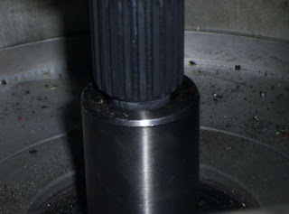

Next we'll finish shaft parts and mate the shafts together. Then it should be fairly easy to put the gearbox and motor into the HR-EV. I hope we can do this before the New Year to have a stronger reason to celebrate :)
2008-12-05
Motor arrived and works started, BMS prototype in progress
My Warp 9 motor arrived in November - heavy beast. I've taken the ICE out from Honda. The gearbox and Warp9 were taken to metal workshop to produce the adapter plate with perfect center alignment. Adapter plate will be produced from 12mm aluminum sheet with the 30mm spacer for the motor flange. No clutch. Shaft adapter will be done from original clutch disk part bolted on steel disk mounted on Warp9 shaft.
As told earlier I will make my own integrated Battery management and Car management system with instruments. So far made following progress on it:
Equipment arrived since last post:
Motor: NetGain Warp 9
BMS: various chips and sensors
Ordered:
Batteries: 45 Thundersky 90Ah LiFePO4s
Vacuum pump: Mes-Dea ( haven't arrive yet)
BCMS: various sensors
Need to decide and order:
Battery charger: haven't decided yet
BCMS: haven't decided which cheap Pocket PC to take as a basis for dashboard screen
Power steering: would like to find an electric steering actuator similar to used in MGs
Work done:
ICE taken out. Warp9 adapter plate started. BMS battery module schematics design and programming almost finished. BCMS design guidelines decided. BCMS master module prototype started. Simple PC software for managing batteries made.
To-Do list: (Long... but main things are generaly listed in no particular order. Later smaller subtasks would be put in detail)
As told earlier I will make my own integrated Battery management and Car management system with instruments. So far made following progress on it:
- Battery Module prototype made and programmed.
 Tests ongoing on model Lithium Polymer batteries. It is nicely balancing the 3-cell pack controlled by PC software via serial link. One module schematic is shown here:
 It is derived from a nice project being developed by Peter Perkins at http://www.batteryvehiclesociety.org.uk/forums/viewtopic.php?t=1245 .
- Once I finish testing I'll design and order PCBs along with all electronic parts needed for them.


- Master module prototyping started with real-time OS launched. Comms and several sensors tested. The core system will be based on ATmega 640 microcontroller. Interface will be provided on Pocket PC display running the GUI software which communicates to master module and displays graphical result. The screen will be integrated in the dashboard to blend into interior design.
- Ordered more sensors chips to have various measurement inputs.
Equipment arrived since last post:
Motor: NetGain Warp 9
BMS: various chips and sensors
Ordered:
Batteries: 45 Thundersky 90Ah LiFePO4s
Vacuum pump: Mes-Dea ( haven't arrive yet)
BCMS: various sensors
Need to decide and order:
Battery charger: haven't decided yet
BCMS: haven't decided which cheap Pocket PC to take as a basis for dashboard screen
Power steering: would like to find an electric steering actuator similar to used in MGs
Work done:
ICE taken out. Warp9 adapter plate started. BMS battery module schematics design and programming almost finished. BCMS design guidelines decided. BCMS master module prototype started. Simple PC software for managing batteries made.
To-Do list: (Long... but main things are generaly listed in no particular order. Later smaller subtasks would be put in detail)
- Install the gearbox and motor when adapter plate finished
- Make battery boxes once batteries arrive
- Design the platform for controller and electronics installation
- Decide about charger ( might design my own 2kW charger...)
- Finish BMS battery modules design and order PCBs and components, build the modules
- Make a BCMS master prototype to perform basic functions to make a first drive-test safe for me and for equipment
- Design and laydown all the power and signaling cabling in the car
- Make a dashboard design change to integrate the BCMS Pocket PC screen
- Develop a software for Pocket PC to indicate main parameters
- Build a cabin heater
- Build power brakes system
- Decide upon and build a power steering system
2008-10-15
Starting my HR-V to HR-EV conversion blog
This is my first entry to log my experiences on conversion of Honda HR-V to electric vehicle. I've decided to do it since my current Subaru is quite old and I want my next car to be electric. There are no affordable electric cars available yet so I've decided to do my own conversion in similar way as many people around the world already done. In the beginning I estimated this conversion to take about 3 months but now I see it would take much longer since I decided to take more expensive components than initially thought and that makes funding the project stretched longer in time.
 It is nice golden yellow 3-door 4WD SUV

I like the look from the back too
 The hood opened before starting to take all unneeded mechanical parts
At this moment I have following components:
Donor car: Honda HR-V '99 4WD
Controller: Kelly KDH16501
DC-DC converter: Kelly 144V to 13.8V, 25A
Throttle: Kelly hall throttle pedal 0-5V
Contactors: Kelly 400A
Shunt: 500A 50mV
Instrument: Westach ammeter

Ordered:
Motor: NetGain Warp 9
Vacuum pump: Mes-Dea
Need to decide and order:
Batteries: most likely TS LiFePO4
Battery charger: haven't decided
BMS: will make my own...
Car management system / instruments: will make my own integrated to BMS...
Work done:
Not much yet. Bought the donor car, started stripping it down, bought some components. More information on progress should come in next posts as I make bigger steps.
 It is nice golden yellow 3-door 4WD SUV
I like the look from the back too
 The hood opened before starting to take all unneeded mechanical parts
At this moment I have following components:
Donor car: Honda HR-V '99 4WD
Controller: Kelly KDH16501
DC-DC converter: Kelly 144V to 13.8V, 25A
Throttle: Kelly hall throttle pedal 0-5V
Contactors: Kelly 400A
Shunt: 500A 50mV
Instrument: Westach ammeter

Ordered:
Motor: NetGain Warp 9
Vacuum pump: Mes-Dea
Need to decide and order:
Batteries: most likely TS LiFePO4
Battery charger: haven't decided
BMS: will make my own...
Car management system / instruments: will make my own integrated to BMS...
Work done:
Not much yet. Bought the donor car, started stripping it down, bought some components. More information on progress should come in next posts as I make bigger steps.
Subscribe to:
Posts (Atom)