I've done some good progress on motor and gearbox works. There was a great deal of help from my friend Gytis who runs the garage I'm working in on my HR-EV!
I've got the manufactured parts from workshop: gearbox adapter plate spacer disk, shaft coupler flange disk, 8 spacer rings for clutch parts assembly and 4 studs for motor which have 3/8 abnormal thread on one end and normal M10 on the other :) Manufacturing cost me around $250 which was not cheap but much less than original quote I've received. Although I couldn't avoid quirks which I'll have to sort with the workshop guys tomorrow.
The quirk was manufactured shaft coupler disk. It looked alright at first glance.
 But when trying to bolt it to clutch parts the holes were not aligning by some 2mm! Initially I thought I've made an error making measurements or the drawing which was given to the workshop. I've measured clutch holes positions again and got 47mm from the center. I took my drawing and it said 47mm too.
 The holes on actual part were 45mm from the center. So I'll have to bring it workshop for re-drilling the holes in correct places offsetting them by 45 degrees. I could have done this myself but I paid healthy money for it so I should expect the work to be done for it. That is not counting the semi-damaged part. This stopped the works on it for the weekend but we could still progress with gearbox adapter plate.
We finished the thick motor spacer disk holes and studs for them so they fit tight in their places. For now just placed them on copper grease for easier work while working on center alignment. Later we'll put them on bolt glue in the motor so they stay firmly in their places in motor.

Next we drilled the holes in thinner gearbox adapter plate and mated it to gearbox.

After this we attached a circular our own assembled drawing device to gearbox shaft and drew the circle rotating the gearbox shaft by clutch part.

Then according to drawn outer line placed the thick motor spacer disk and aligned to match the center position. Our estimated centering error with this method should be something like 0.1-0.3mm which should be fine for this assembly using clutch spring damper. The thick spacer holes were used as drill guides for drilling the holes in exact locations for thinner one.

After that we put motor vertically and put gearbox on it.

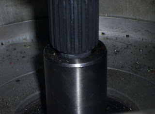
You can see that gearbox shaft goes inside motor's shaft end hole as was designed leaving 2mm space. Shafts centers alignment looks ok. We'll have to check it once we have the shaft adapter disk corrected tomorrow.


No comments:
Post a Comment