I have recently posted a video of driving my EV on YouTube. Put some music on it from local electronic music band "Mind Engineers" . Enjoy.
I am still working to make the car street legal. We had preliminary inspection with transportation experts and agreed on several main points to be done before final certification:
- Emergency disconnect "Red Button"
- Comparing information of cabin air heater element, brake booster and power steering between original components and new replacements
- Protection cover of power cables underneath the car from physical damage (stones, etc.)
- Marking on high voltage cables with with bright colour (orange or similar)
- Informing driver by sound if he's leaving a drive-active car
- Safety procedures modification for starting and running the car in accordance to EN-1987 standards
- Check the charging connector for compliance to EN IEC-62196
- Preparation of technical documentation of the modification
- Some other smaller ones
As I am the first one to go through such certification in my country it is a bit of learning curve for all of us. But I work with people who have good willing approach and we are gradually solving the problems in our way.
So I am quite busy to finalise these things and finaly get my car certified. I will update the blog with new posts of modifications as I go.
Showing posts with label BMS. Show all posts
Showing posts with label BMS. Show all posts
2010-05-15
3E - Ecologic, Economic, Electric; electric Honda HR-V in exhibition
I had 2 busy weeks lately: first - preparation for showing the car on exhibition BaltTechnika 2010, second - participation in exhibition itself. My friend Marius, professional designer, has prepared the design for the car and materials for exhibition. During that the new name for this car has developed - 3E - Ecologic, Economic, Electric which has become a logo of this car. So my working project name "HR-EV" is now 3E.
New web site has started http://www.emobilis.lt/ for the car and activity which is just basic info about the car and the controller for it which is named EVMS - Electric Vehicle Management System. This is the name for the development the management system which previously called BCMS (until I included the motor controller in it as well). Info in lithuanian was put first.
The exhibition was quite successful with a lot of attention from visitors and media. This might inspire further development of the product or some more EV conversions in our country.
Here are some photos from Exhibition.


Some more photos of the car outside:

The photos of components arrangement inside:


And here are some pictures of EVMS (Controller, BMS, safety systems in one) touchscreen display which is implemented on Windows mobile device Ipaq hx4700.
The display graphical user interface software is flexible so it can be arranged in many different pages with different indicators on each page showing the parameters sent from main controller module. The layout, indicators, colours, graphics can be adjusted to liking and match the interior of the car.
Here is the Main page showing battery voltage, current, power, energy, momentary and average consumption, distance traveled today and estimated distance left.

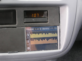
Here is the battery cells status screen showing voltage, temperature and balancing voltage of each cell plus average and total voltage of all cells.
Here is the consumption screen showing battery charge, estimated distance left, distance, energy consumption of this trip and today plus average and momentary consumption.

Here is the screen voltages. It shows voltage, current and power of main battery, motor and 12V battery plus position of accelerator pedal at the bottom.

This Charging screen shows charging stage. It shows voltage, current and power set for charger and actual. It also shows cells minimum, average and maximum voltages. Two buttons at the bottom allow you to select the charging rate: slow for 220V/10A socket and fast for 220V/16A socket.

Here is Temperatures screen which shows temperatures of controller (IGBTs power stage), motor, battery minimum and maximum, interior and exterior.

And lastly the main menu which allows to select you the information page you want. The time on stock car clock is wrong as I forgot to set it right :). Note the small card at bottom left? That is the SD card which carries the screen configuration and recorded parameters log files. It records the files constantly producing one file per day.

Here is a short movie of display in action:
New web site has started http://www.emobilis.lt/ for the car and activity which is just basic info about the car and the controller for it which is named EVMS - Electric Vehicle Management System. This is the name for the development the management system which previously called BCMS (until I included the motor controller in it as well). Info in lithuanian was put first.
The exhibition was quite successful with a lot of attention from visitors and media. This might inspire further development of the product or some more EV conversions in our country.
Here are some photos from Exhibition.


Some more photos of the car outside:

The photos of components arrangement inside:


And here are some pictures of EVMS (Controller, BMS, safety systems in one) touchscreen display which is implemented on Windows mobile device Ipaq hx4700.
The display graphical user interface software is flexible so it can be arranged in many different pages with different indicators on each page showing the parameters sent from main controller module. The layout, indicators, colours, graphics can be adjusted to liking and match the interior of the car.
Here is the Main page showing battery voltage, current, power, energy, momentary and average consumption, distance traveled today and estimated distance left.

Here is the battery cells status screen showing voltage, temperature and balancing voltage of each cell plus average and total voltage of all cells.

Here is the consumption screen showing battery charge, estimated distance left, distance, energy consumption of this trip and today plus average and momentary consumption.

Here is the screen voltages. It shows voltage, current and power of main battery, motor and 12V battery plus position of accelerator pedal at the bottom.

This Charging screen shows charging stage. It shows voltage, current and power set for charger and actual. It also shows cells minimum, average and maximum voltages. Two buttons at the bottom allow you to select the charging rate: slow for 220V/10A socket and fast for 220V/16A socket.

Here is Temperatures screen which shows temperatures of controller (IGBTs power stage), motor, battery minimum and maximum, interior and exterior.

And lastly the main menu which allows to select you the information page you want. The time on stock car clock is wrong as I forgot to set it right :). Note the small card at bottom left? That is the SD card which carries the screen configuration and recorded parameters log files. It records the files constantly producing one file per day.

Here is a short movie of display in action:
2009-06-23
BMS Charging System Works!
I've been working intensively on my battery modules, BMS and charger to get them working together. So here's the story in sequence.
Fun with SMD microbs
My battery modules are made from small SMD components which I was never working with before. My previous electronics experience was with bigger sized and DIP components. So it was a new learning experience as I had with many other areas on this project - a lot of fun and satisfying moments.
On the first PCB I tried soldering these components with fine tip soldering iron which worked but I wanted to try a different way. Popular way which is also used in industry is placing components on the PCB with SMD soldering paste and treating it with heat at which solder melts. In serial manufacturing the boards are soldered by putting them in special owens.
Alternative for manual soldering is soldering with hot air. I used the hot air way although owen method should work too if had an owen. In the beginning I used some small Portasol gas soldering iron with air blower tip. It worked fine but I was not happy that I cannot control the temperature of the air and I can only have a rough estimate of this temperature. So I bought a hot air soldering station which I know I'll use in future too. Soldering the boards with it was an easy job. The tedious but not difficult part of the process was putting SMD paste and placing the components on the boards before blowing them with hot air. No problem with shaky hands and sight. Surprisingly to myself I found it easiest to do it without any magnifying goggles although I had them. My wife said I could be a surgeon. I guess I could :-)
Anyway I liked the process and I think it would have taken me notably longer with traditional components with all legs bending, sticking, soldering and crimping. It has taken me around 2-3 hours for soldering each board consisting of 10 battery modules. So manufacturing 45 modules was not bad at all.


Battery module features
I'd like to list features that my designed battery modules have. It was quite long and iterative design and development process and I am happy I finished it. I like the final result.
Here is the list of battery module version 1 features:
- Balancing type: shunting current controlled by microcontroller
- Microcontroller: ATMEL ATtiny25V
- Operating voltage range: 2...5V
- Shunting resistance: 2.35Ohm 10 Watt
- Shunting current control: Pulse Width Modulation
- Communication protocol: custom serial protocol with LIN style sync frame
- Comm. bit rate: 2400bps (may work up to 9600bps or more)
- Comm. line: 1 wire going from module to module in chain - very easy and tidy installation
- Communication isolation: 1 Optocoupler on first module on the 2-wire input from BMS and 1 on the output to BMS over 2 wires back
- Measured parameters: Cell voltage, Cell temperature and shunting PWM value
- Voltage measurement accuracy: +/- 0.01V
- Temperature measurement accuracy: +/- 5C
- Parameter read commands: Read Voltages from all cells, Read Voltage from specific cell, Read Temperatures from all cells, Read Temperature from specific cell, Read PWM values from all cells, Read PWM value from specific cell
- Parameter write commands: Write balancing voltage to all cells, Write balancing voltage to specific cell, Write temperature calibration to all cells, Write temperature calibration to specific cell, Write max allowed temperature to all cells, Write max allowed temperature to specific cell, Write max allowed PWM to all cells, Write max allowed PWM to specific cell, Write cell IDs to all cells and read back the cell count.
- Automatic cell enumeration and counting via Write cell IDs command from BMS
- Automatic microcontroller sleep on idle (no comm from BMS for some time - like 60 seconds) to save power
- Automatic shunting current control via PWM to keep preset balancing voltage
- In-circuit microcontroller reprogamming capability via 1-wire debugWire interface
- LED indication of communication activity and PWM balancing mode
- Voltage spikes protection of the circuit supply, input and output signals
- Low cost due to carefully selected components and their count on each module
BCMS prototype board upgrade with CAN bus and Real-Time clock
I've added Microchip's MCP2515 CAN controller with Philips PCA82C260 CAN interface to be able to communicate with my new PFC 3kW charger from www.hztiecheng.com. My ATmega640 talks to MCP2515 over SPI interface. After few evenings of programming I made CAN bus work and my BCMS started talking to the charger. I can set charger voltage and current and enable charging. Charger returns me actual voltage and current plus the status with info such as overtemperature or battery fault flags. The charger model I have is named 144V/16A but as I learned it is capable of producing currents up to 20A.
Then I worked on programming the charging algorithm which would be suitable for my battery pack. It was done quite quickly to the point where I needed to have some reliable timekeeping. So I decided to finaly implement the real time clock (RTC) into my BCMS.
The RTC is made on Maxim DS1307 chip which is talking to my main processor over I2C interface. It has a Lithium backup button battery to keep the clock running when all the batteries are disconnected.


BMS charging demo
Finally here is a short movie demonstrating my BMS working with charger to charge and balance the battery pack
At this point I will be starting to put all electronics into control box, test it and then put into the car and connect to the motor. I'll put battery boxes with batteries in the back trunk first to have test drives and tune the system. Later I'll put them under car's belly as intended.
Fun with SMD microbs
My battery modules are made from small SMD components which I was never working with before. My previous electronics experience was with bigger sized and DIP components. So it was a new learning experience as I had with many other areas on this project - a lot of fun and satisfying moments.
On the first PCB I tried soldering these components with fine tip soldering iron which worked but I wanted to try a different way. Popular way which is also used in industry is placing components on the PCB with SMD soldering paste and treating it with heat at which solder melts. In serial manufacturing the boards are soldered by putting them in special owens.
Alternative for manual soldering is soldering with hot air. I used the hot air way although owen method should work too if had an owen. In the beginning I used some small Portasol gas soldering iron with air blower tip. It worked fine but I was not happy that I cannot control the temperature of the air and I can only have a rough estimate of this temperature. So I bought a hot air soldering station which I know I'll use in future too. Soldering the boards with it was an easy job. The tedious but not difficult part of the process was putting SMD paste and placing the components on the boards before blowing them with hot air. No problem with shaky hands and sight. Surprisingly to myself I found it easiest to do it without any magnifying goggles although I had them. My wife said I could be a surgeon. I guess I could :-)
Anyway I liked the process and I think it would have taken me notably longer with traditional components with all legs bending, sticking, soldering and crimping. It has taken me around 2-3 hours for soldering each board consisting of 10 battery modules. So manufacturing 45 modules was not bad at all.
Here is one batch of 10 manufactured boards

And here is a massive array of 36 as 9 others were already sitting on the cells as I was taking this photo :)

Battery module features
I'd like to list features that my designed battery modules have. It was quite long and iterative design and development process and I am happy I finished it. I like the final result.
Here is the list of battery module version 1 features:
- Balancing type: shunting current controlled by microcontroller
- Microcontroller: ATMEL ATtiny25V
- Operating voltage range: 2...5V
- Shunting resistance: 2.35Ohm 10 Watt
- Shunting current control: Pulse Width Modulation
- Communication protocol: custom serial protocol with LIN style sync frame
- Comm. bit rate: 2400bps (may work up to 9600bps or more)
- Comm. line: 1 wire going from module to module in chain - very easy and tidy installation
- Communication isolation: 1 Optocoupler on first module on the 2-wire input from BMS and 1 on the output to BMS over 2 wires back
- Measured parameters: Cell voltage, Cell temperature and shunting PWM value
- Voltage measurement accuracy: +/- 0.01V
- Temperature measurement accuracy: +/- 5C
- Parameter read commands: Read Voltages from all cells, Read Voltage from specific cell, Read Temperatures from all cells, Read Temperature from specific cell, Read PWM values from all cells, Read PWM value from specific cell
- Parameter write commands: Write balancing voltage to all cells, Write balancing voltage to specific cell, Write temperature calibration to all cells, Write temperature calibration to specific cell, Write max allowed temperature to all cells, Write max allowed temperature to specific cell, Write max allowed PWM to all cells, Write max allowed PWM to specific cell, Write cell IDs to all cells and read back the cell count.
- Automatic cell enumeration and counting via Write cell IDs command from BMS
- Automatic microcontroller sleep on idle (no comm from BMS for some time - like 60 seconds) to save power
- Automatic shunting current control via PWM to keep preset balancing voltage
- In-circuit microcontroller reprogamming capability via 1-wire debugWire interface
- LED indication of communication activity and PWM balancing mode
- Voltage spikes protection of the circuit supply, input and output signals
- Low cost due to carefully selected components and their count on each module
BCMS prototype board upgrade with CAN bus and Real-Time clock
I've added Microchip's MCP2515 CAN controller with Philips PCA82C260 CAN interface to be able to communicate with my new PFC 3kW charger from www.hztiecheng.com. My ATmega640 talks to MCP2515 over SPI interface. After few evenings of programming I made CAN bus work and my BCMS started talking to the charger. I can set charger voltage and current and enable charging. Charger returns me actual voltage and current plus the status with info such as overtemperature or battery fault flags. The charger model I have is named 144V/16A but as I learned it is capable of producing currents up to 20A.
Then I worked on programming the charging algorithm which would be suitable for my battery pack. It was done quite quickly to the point where I needed to have some reliable timekeeping. So I decided to finaly implement the real time clock (RTC) into my BCMS.
The RTC is made on Maxim DS1307 chip which is talking to my main processor over I2C interface. It has a Lithium backup button battery to keep the clock running when all the batteries are disconnected.
Here is the photo of the board with the processor off

And here is with the processor on

BMS charging demo
Finally here is a short movie demonstrating my BMS working with charger to charge and balance the battery pack
At this point I will be starting to put all electronics into control box, test it and then put into the car and connect to the motor. I'll put battery boxes with batteries in the back trunk first to have test drives and tune the system. Later I'll put them under car's belly as intended.
2009-05-10
BCMS and Battery Boxes
I caught some nasty flu on Thursday and needed to sit at home during almost whole weekend. Luckily wife with baby were out during it - visiting parents, so they were safe. Once I was feeling better I resumed some works on electronics and programming. I sent an order for battery module 45 PCBs. I expect to have them on Friday.

I've started programming the PDA graphical user interface. I'll use IPAQ or similar PDA with PocketPC 2003 system which will be mounted in the dashboard and give all information about car, batteries, temperatures, etc. For starters I just made it read the serial output sentences which are generated by BCMS. The protocol is NMEA which is widely used in GPS devices. I've created some custom sentence names which are used in my BCMS. The idea is that I'll have all parameters information along with GPS position of the car which will help car performance analysis after. Below is PDA emulator's program's simple screen which reads the data from serial port and displays in simple text fields. The parameters displayed are actually measured by BCMS.

When I got better on Sunday afternoon I went to garage and made a short session working on battery boxes. I welded the top mounting flange with one hole for initial mounting of the box. I also welded a M8 bolt part at the botom of the box where the batteries are being put. This bolt will be used to secure and press the batteries with V-shaped frame shown below. This will prevent any possible swelling of the cells.

Next will be a lot of grinding of the boxes to remove excess metal from the welds and improve aesthetic view. Nasty part will be cleaning the welds in inner corners of the boxes as it is not yet done properly. Then I will put stainless steel sheet into the boxes walls and they will be almost finished. Almost... There will be plastic retainer bars inside to stop cells from bouncing in the box. And also some plastic or maybe metal sheet cover on top of the boxes with openings at both ends to allow access for boxes interconnections.
2009-03-24
Electric vehicle brake arrived!
It's been a while since my last post about HR-V conversion and have you been questioning why? It is because the "Electric vehicle brake" has arrived on Feb 21st. The brake is 53cm long and 3.56kg heavy :)
That's right- I have a firstborn child, a boy whose name is Herkus!
Here is my son Herkus first days of his life in this world.

Here is Herkus and me. No, I'm not Chinese - it is less sleep that I got during these days.

He is an EV brake but he is not an EV stopper and I believe the day will come when he will be an EV accelerator. I continue working on EV although naturally the speed is less with the brake on :)
I've done good progress on several things, which I will post more pictures and detail in new posts shortly:
- Battery Voltage and Current measurement circuit is made and programmed which is communicating to BCMS master module to report measured voltages and currents. Voltage measurement step is 0.2V up to 204V. Current is measured up to 512A with 0.5A steps.
- Made measurements and brainstorming about battery placement in the car. Decided to put all batteries in 5 trays with 9 cells each where the fuel tank used to be - plenty of space there in HR-V. The trays will be fit from below so car lift would be needed. Made one battery tray frame from stainless steel angles to verify the concept.
- Designed the box where controller, contactor, accessory charger, shunt, accelerator pot and other electronics components will be placed securely and safely without any potential of high and low voltages to be touched by water or uncareful hands. Already built the main parts of the box and ready to place the components in. Now working to finish the controller box and start fitting the components inside.
- As Gytis has moved from his garage I now continue working in my small garage below my apartment block. It is small, much less equiped but is much easier to come down to work in the evenings.
Will put more info and pictures in upcomming posts. Stay tuned!
2009-01-23
Batteries are home!
Long waiting is over - batteries arrived to where they belong :) I've received 45 TS-LFP90AHA batteries for my HR-EV after more than two months waiting. They've been sailing from Shenzhen in China to Hamburg in Germany and then to Klaipeda in Lithuania - a long trip.

Shortly after I've opened the boxes to see what's inside. I found nicely printed manual and quality certificate. Quality certificate has lots of useful information in Chinese :) User nice manual was the same as pdf available from ThunderSky site. Beneath white cover I found a surprise - batteries :).


The road to the future :)
While I was waiting for the batteries I've been working a lot on BCMS prototype electronics and programming. Here's a brief update about the progress:
- RealTime OS launched on ATmega640
- Serial communications programming wired and programmed - talking to PC now
- Connected to battery modules (at bottom) via opto-coupled serial port and launched battery voltages reading for BMS operation. It ballances Lithium Polymer cells within 0.02V of each other.
- Wired and programmed MLX90215 sensor (small board assembled on the left) so I can measure current of up to 10 Amps to test the concept. The finished sensor will be able to measure up to 700A from batteries and to the motor.
- Wired a contactor control circuit (simple IRL3705 MOSFET switch) and programmed its control
- Wired and programmed 12V line voltage measurement using mega's ADC
- Wired and programmed DS18B20 sensors for BCMS, Controller, Motor, Outside, Inside and Batteries temperature sensing.
- Started wiring a slot for SD/MMC card where the HR-EV's parameters log would be stored
- Some small stuff...

There are many things left to do on electronics until I start the first test of the car:
- Finalize battery module schematics, programming and PCB design, try final prototype on real battery and then order parts and PCBs
- Make schematics/wiring and programming of opto-isolated battery voltage measurement
- Make motor RPM sensor using MLX90217, wire it and program RPM calculation
- Wire gearbox speed sensor and program the speed calculation
- Make throttle sensing and control schematic and programming
- Wire digital inputs like key switch, charger on, throttle idle, gearbox neutral etc.
- Program the safety and control. Basically it should shut off main contactor if any important parameter goes critically off.
Well, there is much much more. One thing - I still haven't got the charger. In the beginning I thought about Zivan NG3 but now I'm not so sure. Still have to decide... and order it.
Of course there are lots of mechanics works to do as well. I'll update as I progress.
I've taken them from warehouse after customs clearance in my trusty Subaru.

Shortly after I've opened the boxes to see what's inside. I found nicely printed manual and quality certificate. Quality certificate has lots of useful information in Chinese :) User nice manual was the same as pdf available from ThunderSky site. Beneath white cover I found a surprise - batteries :).

Here's a video shot from breathtaking moment :-D
The look at the battery itself.
The look at the battery itself.

All the batteries read voltage of 3.30V or 3.31V - GOOD!

The road to the future :)

While I was waiting for the batteries I've been working a lot on BCMS prototype electronics and programming. Here's a brief update about the progress:
- RealTime OS launched on ATmega640
- Serial communications programming wired and programmed - talking to PC now
- Connected to battery modules (at bottom) via opto-coupled serial port and launched battery voltages reading for BMS operation. It ballances Lithium Polymer cells within 0.02V of each other.
- Wired and programmed MLX90215 sensor (small board assembled on the left) so I can measure current of up to 10 Amps to test the concept. The finished sensor will be able to measure up to 700A from batteries and to the motor.
- Wired a contactor control circuit (simple IRL3705 MOSFET switch) and programmed its control
- Wired and programmed 12V line voltage measurement using mega's ADC
- Wired and programmed DS18B20 sensors for BCMS, Controller, Motor, Outside, Inside and Batteries temperature sensing.
- Started wiring a slot for SD/MMC card where the HR-EV's parameters log would be stored
- Some small stuff...

There are many things left to do on electronics until I start the first test of the car:
- Finalize battery module schematics, programming and PCB design, try final prototype on real battery and then order parts and PCBs
- Make schematics/wiring and programming of opto-isolated battery voltage measurement
- Make motor RPM sensor using MLX90217, wire it and program RPM calculation
- Wire gearbox speed sensor and program the speed calculation
- Make throttle sensing and control schematic and programming
- Wire digital inputs like key switch, charger on, throttle idle, gearbox neutral etc.
- Program the safety and control. Basically it should shut off main contactor if any important parameter goes critically off.
Well, there is much much more. One thing - I still haven't got the charger. In the beginning I thought about Zivan NG3 but now I'm not so sure. Still have to decide... and order it.
Of course there are lots of mechanics works to do as well. I'll update as I progress.
2008-12-23
Adapter and BCMS works ongoing
The gearbox adapter production is in progress although not as fast as I would have liked. The gearbox plate was cut to gearbox contour with UHP water cutter. Spacer produced on lathe. Adapter disk production is on final. The gearbox was brought to workshop for all parts mating. Sorry - no pictures yet. I hope I'll collect it before Christmas and install motor straight after Christmas.
I was fighting with BCMS Atmega640 over the weekend and could not get it running stable - it was driving me nuts. And yesterday night I just came with fresh view and approached the problem from different angle. I found the root cause which was quite silly that I don't want to talk about. I should get it running OS performing basic comm tasks in few days now. I'd like to get it talking to my battery modules prototypes and to PC. Then I'll focus on building the main contactor control, temperature, voltage and current measurement circuits as these would be required soonest to measure main parameters for safe testing.
I was fighting with BCMS Atmega640 over the weekend and could not get it running stable - it was driving me nuts. And yesterday night I just came with fresh view and approached the problem from different angle. I found the root cause which was quite silly that I don't want to talk about. I should get it running OS performing basic comm tasks in few days now. I'd like to get it talking to my battery modules prototypes and to PC. Then I'll focus on building the main contactor control, temperature, voltage and current measurement circuits as these would be required soonest to measure main parameters for safe testing.
2008-12-18
Motor adapter and BMS works ongoing
Last few days been involved in other activities and little time was left for the EV project. Anyway I had time to arrange all activities for gearbox adapter and shaft coupler. I've purchased the materials and brought them to workshops. Realistic timing is to have the parts made for the beginning of next week.
There was some progress on Battery Module PCB design. I've made it to the point where it is nearly finished and I could finalize it and send the design files to PCB manufacturers. But I've decided to wait until my batteries arrive and make a final fit check on actual cell before ordering PCBs production. My batteries are still sailing to me and according to the documents I should expect them around December 26th.
So far my nearly finished design is shown below. Just top copper is shown for clarity.


For now I'll put it asside and will resume work on master module on recently received ATmega640 MCU and various sensors. I've decided that I won't produce any PCB for master until I have fully functioning prototype working in the car. Only then I'll produce the PCB mostly with SMD components for the car computer.
Below is the initial board with MCU on adapter board. It will start growing with various components around it quickly and and I'll adapt the Real-Time Operating Systerm (RTOS) for it as I did for ATmega16.

2008-12-08
Sensor chips arrived
My Melexis MLX 90215, 90217 and Allegro ACS754LCB-100-PFF sensor chips arrived:

They are kind of urging me to finish the work on battery modules and get back to BCMS master module design and prototyping. The functions of these received chips will be following:

They are kind of urging me to finish the work on battery modules and get back to BCMS master module design and prototyping. The functions of these received chips will be following:
- MLX 90215 will measure the high currents (up to 650A) from batteries and to the motor.
- MLX 90217 will measure the RPM of the motor on teethed gear mounted on the accessory shaft of my Warp 9
- ACS754 will measure the charging current, DC/DC converter current and accessory battery draw current
2008-12-05
Motor arrived and works started, BMS prototype in progress
My Warp 9 motor arrived in November - heavy beast. I've taken the ICE out from Honda. The gearbox and Warp9 were taken to metal workshop to produce the adapter plate with perfect center alignment. Adapter plate will be produced from 12mm aluminum sheet with the 30mm spacer for the motor flange. No clutch. Shaft adapter will be done from original clutch disk part bolted on steel disk mounted on Warp9 shaft.
As told earlier I will make my own integrated Battery management and Car management system with instruments. So far made following progress on it:
Equipment arrived since last post:
Motor: NetGain Warp 9
BMS: various chips and sensors
Ordered:
Batteries: 45 Thundersky 90Ah LiFePO4s
Vacuum pump: Mes-Dea ( haven't arrive yet)
BCMS: various sensors
Need to decide and order:
Battery charger: haven't decided yet
BCMS: haven't decided which cheap Pocket PC to take as a basis for dashboard screen
Power steering: would like to find an electric steering actuator similar to used in MGs
Work done:
ICE taken out. Warp9 adapter plate started. BMS battery module schematics design and programming almost finished. BCMS design guidelines decided. BCMS master module prototype started. Simple PC software for managing batteries made.
To-Do list: (Long... but main things are generaly listed in no particular order. Later smaller subtasks would be put in detail)
As told earlier I will make my own integrated Battery management and Car management system with instruments. So far made following progress on it:
- Battery Module prototype made and programmed.
 Tests ongoing on model Lithium Polymer batteries. It is nicely balancing the 3-cell pack controlled by PC software via serial link. One module schematic is shown here:
 It is derived from a nice project being developed by Peter Perkins at http://www.batteryvehiclesociety.org.uk/forums/viewtopic.php?t=1245 .
- Once I finish testing I'll design and order PCBs along with all electronic parts needed for them.


- Master module prototyping started with real-time OS launched. Comms and several sensors tested. The core system will be based on ATmega 640 microcontroller. Interface will be provided on Pocket PC display running the GUI software which communicates to master module and displays graphical result. The screen will be integrated in the dashboard to blend into interior design.
- Ordered more sensors chips to have various measurement inputs.
Equipment arrived since last post:
Motor: NetGain Warp 9
BMS: various chips and sensors
Ordered:
Batteries: 45 Thundersky 90Ah LiFePO4s
Vacuum pump: Mes-Dea ( haven't arrive yet)
BCMS: various sensors
Need to decide and order:
Battery charger: haven't decided yet
BCMS: haven't decided which cheap Pocket PC to take as a basis for dashboard screen
Power steering: would like to find an electric steering actuator similar to used in MGs
Work done:
ICE taken out. Warp9 adapter plate started. BMS battery module schematics design and programming almost finished. BCMS design guidelines decided. BCMS master module prototype started. Simple PC software for managing batteries made.
To-Do list: (Long... but main things are generaly listed in no particular order. Later smaller subtasks would be put in detail)
- Install the gearbox and motor when adapter plate finished
- Make battery boxes once batteries arrive
- Design the platform for controller and electronics installation
- Decide about charger ( might design my own 2kW charger...)
- Finish BMS battery modules design and order PCBs and components, build the modules
- Make a BCMS master prototype to perform basic functions to make a first drive-test safe for me and for equipment
- Design and laydown all the power and signaling cabling in the car
- Make a dashboard design change to integrate the BCMS Pocket PC screen
- Develop a software for Pocket PC to indicate main parameters
- Build a cabin heater
- Build power brakes system
- Decide upon and build a power steering system
2008-10-15
Starting my HR-V to HR-EV conversion blog
This is my first entry to log my experiences on conversion of Honda HR-V to electric vehicle. I've decided to do it since my current Subaru is quite old and I want my next car to be electric. There are no affordable electric cars available yet so I've decided to do my own conversion in similar way as many people around the world already done. In the beginning I estimated this conversion to take about 3 months but now I see it would take much longer since I decided to take more expensive components than initially thought and that makes funding the project stretched longer in time.
 It is nice golden yellow 3-door 4WD SUV

I like the look from the back too
 The hood opened before starting to take all unneeded mechanical parts
At this moment I have following components:
Donor car: Honda HR-V '99 4WD
Controller: Kelly KDH16501
DC-DC converter: Kelly 144V to 13.8V, 25A
Throttle: Kelly hall throttle pedal 0-5V
Contactors: Kelly 400A
Shunt: 500A 50mV
Instrument: Westach ammeter

Ordered:
Motor: NetGain Warp 9
Vacuum pump: Mes-Dea
Need to decide and order:
Batteries: most likely TS LiFePO4
Battery charger: haven't decided
BMS: will make my own...
Car management system / instruments: will make my own integrated to BMS...
Work done:
Not much yet. Bought the donor car, started stripping it down, bought some components. More information on progress should come in next posts as I make bigger steps.
 It is nice golden yellow 3-door 4WD SUV
I like the look from the back too
 The hood opened before starting to take all unneeded mechanical parts
At this moment I have following components:
Donor car: Honda HR-V '99 4WD
Controller: Kelly KDH16501
DC-DC converter: Kelly 144V to 13.8V, 25A
Throttle: Kelly hall throttle pedal 0-5V
Contactors: Kelly 400A
Shunt: 500A 50mV
Instrument: Westach ammeter

Ordered:
Motor: NetGain Warp 9
Vacuum pump: Mes-Dea
Need to decide and order:
Batteries: most likely TS LiFePO4
Battery charger: haven't decided
BMS: will make my own...
Car management system / instruments: will make my own integrated to BMS...
Work done:
Not much yet. Bought the donor car, started stripping it down, bought some components. More information on progress should come in next posts as I make bigger steps.
Subscribe to:
Posts (Atom)